|
In this
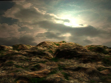
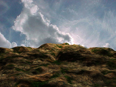
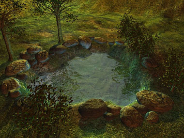
tutorial I show an easy way to make nice ground texture.
Picture on the right shows my result of this tutorial.
|
|
You can do this tutorial without any
texture maps by using procedural maps (Noise, Cellurar and Smoke).
It just doesn't give you as good results. Click
here for an example where's used ONLY "Noise", "Cellurar"
and "Smoke" to make the ground texture.
Let's start.
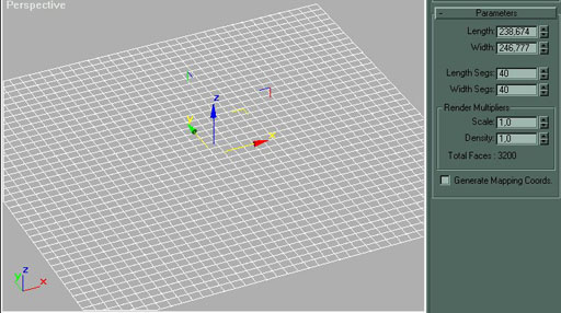
Make a plane (Max 2.x users can make a patch)
Length segs: 40
Width segs: 40
Next step is to make a displacement map (in this tutorial I used
"Smoke" material).
For more detailed ground you can paint your own if you like more control for
your height map.
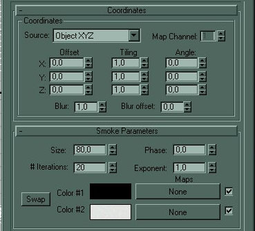
Smoke parameters
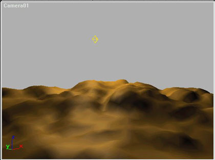
Result after displacement map.
Ok. Now make 2 more copies of your
terrain and move each one a little bit down
and name them from top to bottom: "layer1", "layer2" and
"layer3".
Next open up material editor.
I used following three material slots "Diffuse", "Opacity"
and "Bump"
Diffuse slot:
You should find following textures from your Max package.
Layer 1: Treebark.jpg
Layer 2: Loosedrt.jpg
Layer 3: Evrgren2.jpg
For opacity I used 3D Studio Max 3 material "Gradient Ramp".
Max 2.x users can use "Noise" or "Smoke" maps.
Opacity slot:
Layer 1:
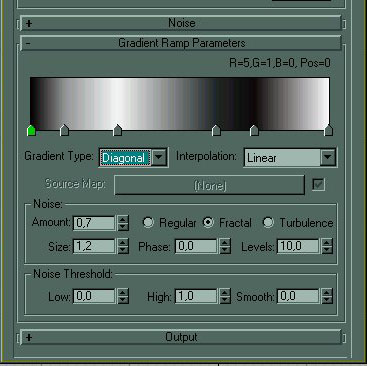
Settings for Layer 1's Gradient Ramp.
Layer 2:
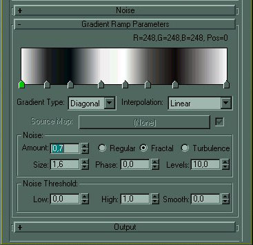
Settings for Layer 2's Gradient Ramp.
You don't have to make exact copies, just make sure that Layer 1 and Layer 2
have different opacity.
Note! I've noticed that if you put too small number to "Size" (less
than 1,0) it won't look good when you render. So size does matter... heh heh....
Layer 3:
NO opacity map (because this is the last layer and we don't want to see through
it)
Bump slot:
For all layers use noise map.
Now it's rendering time.
With any good luck you get good results in
first try, but usually you don't. Then it's back to adjust your opacity
maps
_____________________
You've probably noticed that this method increases your scenes face count alot.
Try this (for Max 3 users, sorry).
When you're happy with your ground texture. Select all the layers and select
"Box Selected" from the menu next to "Quick Render" button.
Now render from top view. Now you can set your resolution which to render. Now
you have a nice ground texture.
Now delete layer 2 and 3 and apply this texture to layer 1.
That's it for the ground.


Now let's watch these two pictures.

This one have background picture in old fashion way.
(You can see that background doesn't fit with the terrain)
This one have background picture in old fashion way.
(You can see that background doesn't fit with the terrain)
Now how is that made you might ask?
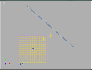 This is how I made it.
See that blue box opposite to camera.
That's where I placed my sky texture and
you can see those 2 lights, which gives right tone for the sky and for the terrain.
(now it match better with the terrain).
If we think any further we'll see that this doesn't work if we are making animation.
Don't worry I've a solution (I think. Ofcourse I haven't tried this, but... it should work).
What if we make a hemisphere over our scene and apply our sky texture on that???
Now where ever you turn your camera you see the sky. AND if you make more layers of that sky
hemisphere you could easily do MOVING clouds by using "Noise".
This is how I made it.
See that blue box opposite to camera.
That's where I placed my sky texture and
you can see those 2 lights, which gives right tone for the sky and for the terrain.
(now it match better with the terrain).
If we think any further we'll see that this doesn't work if we are making animation.
Don't worry I've a solution (I think. Ofcourse I haven't tried this, but... it should work).
What if we make a hemisphere over our scene and apply our sky texture on that???
Now where ever you turn your camera you see the sky. AND if you make more layers of that sky
hemisphere you could easily do MOVING clouds by using "Noise".
I made a picture where I combined both
"Trees" and "Landscape" tutorials.
Olli-Pekka Saastamoinen

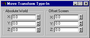
1. Create your scene at the origin.
2. Create Target camera in top viewport.
3. Select camera target, go to
"transform type in" from " tools" and set x=0, y=0, z=0.
(Assuming scene is at origin) (fig.1)
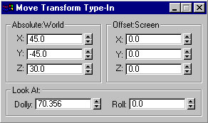
4. Select camera, set
x=45, y=-45 z=30 (fig. 2)
Setting the x and y at 45 gives you the
isometric view on your scene, to modify the distance from your scene, simply
change the x and y values in respect with the distance to preserve the isometric
view. Depending on the angle at which you want to view your tiles, I would
recommend setting the vertical orientation of your camera to 30؛, this way you
will have a tile ratio of 2:1 as in Diablo.
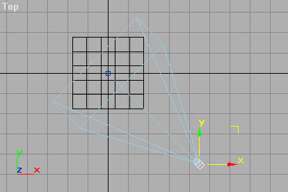
5. fig. 3 shows where your camera should
be positioned in the top viewport after steps 1-4.
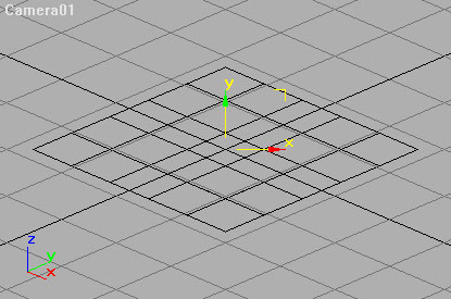
6. fig. 4 shows the isometric view when
viewed through the camera.
 |
Lathe
(Glass).
Return
to 3DS Max tutorials |
|
Local
Coordinates - Teapot. |
|
Extrude
- Logo. |
|
Cloning
and the X form Modiffier - Daisy. |
|
Basic
Keyframing - The Bouncing Ball, part (2). |
|
Boolean
Compound Objects. |
|
Forward
Kinematics - The Robot Arm. |
|
Intro
to Materials - Still Life, part (1). |
|
Sub
object Materials - Still Life, part (2). |
|
Mapping
Coordinates - Still Life, part (3). |
|
|